Originally, this longboard was meant to be built as a 3-wheeled board, and thats how it was designed. I had planned to machine the back “truck” out of aluminum and put a scooter wheel slightly through the hole for the dropdown trucks to keep it mostly level with the front wheels (which as you can see on the CAD render below would have to be bottom mounted). Unfortunately this is not a fusion 360 model so it’s a little bit harder to embed to play around with, but I may look into solutions to add solidworks models to a website.

The logic behind this configuration was reduced mechanical complexity. The motor could be mounted directly to the wooden deck, reducing part count on the steering, and hopefully increase clearance with the ground while keeping all the electronics contained to beneath the board.
The parts were assembled, and a motor mount was even printed.


After building a wooden test part however, it was obvious a few kinks would have to be worked out before that could happen. The board was obviously a lot less stable in this configuration, which led to having to stand way forward on the board, and to have a much less strong stance. This is problematic on a non-powered board already, so adding the acceleration and deceleration of an electric powered one would likely end in me flying off which is obviously not ideal. I still like the idea, but it required too much rebuilding of the deck itself which was simply not practical.
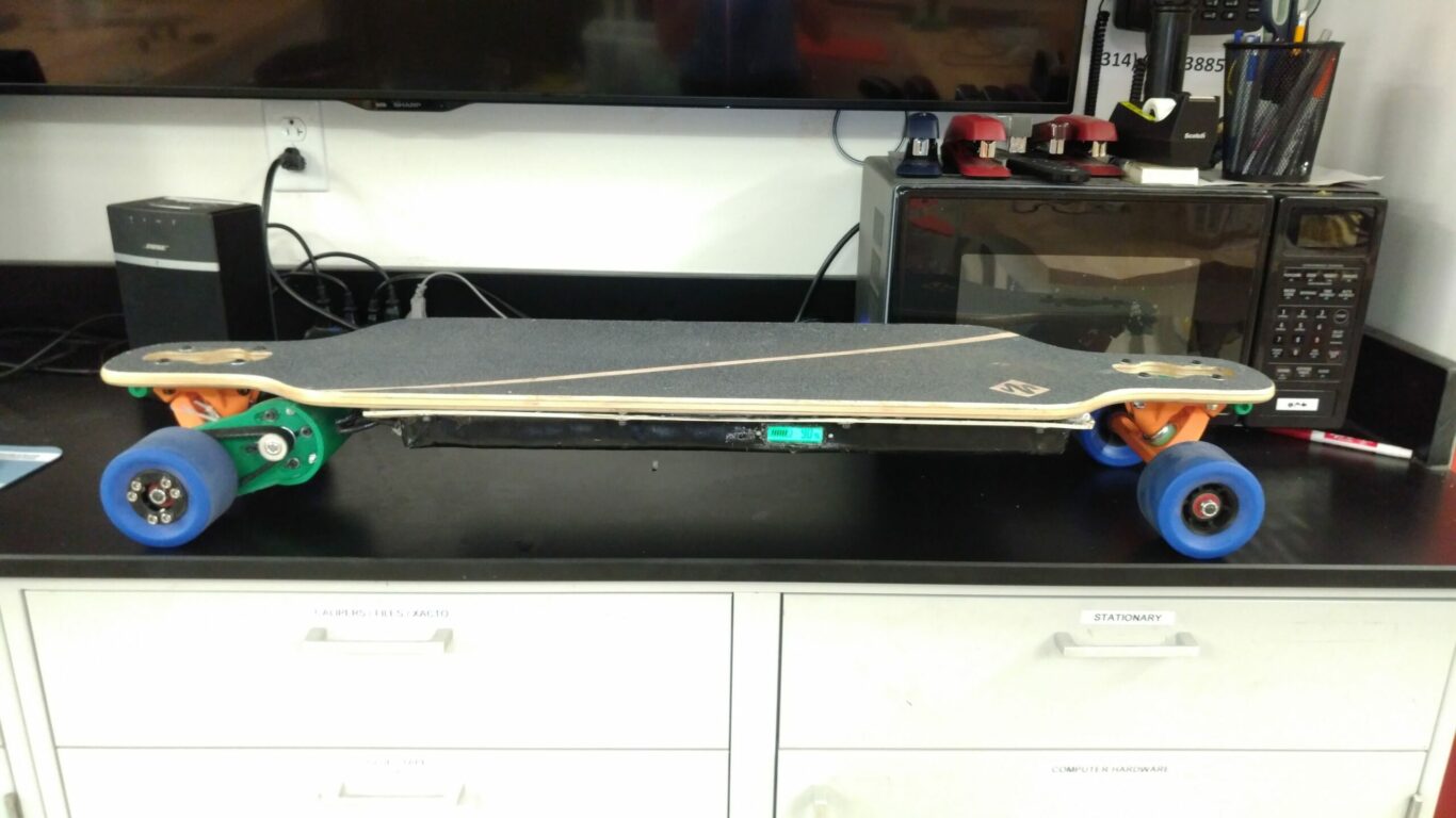
This setback didn’t really stop me from finishing this project however, it just made the output a bit less unique.
I ended up going with a somewhat different battery configuration to allow taking the cells on the plane. The total capacity is over 300Wh which is way above the limit for a single pack, and around the limit for a pair of declared packs to take onboard. A way around this, which mainly has to do with fire safety, is to keep all the cells separately. At ~9Wh each, they are much less of a hazard if one spontaneously bursts in flames.
Another issue I encountered was my VESC being built improperly. It seems one of the thermistors had the wrong specs, to fix it I simply found what the actual component soldered to the board was and fixed it by adjusting the temps in the software to match the actual temperature limits I was aiming for in reality.
This was mainly done because buying a new one would have been expensive, and getting it back to them and waiting for them to ship it back to me would have taken nearly a month. It just took a bit of digging around into the board schematics and figuring out what the issue was, and a quick spreadsheet later I could get back to buidling:
And after that small fix, the motor runs with temperature limits being maintained.